All About Alien Crosstalk Measurement
July 21, 2016 / General, 101 learning, Installation and testing, Upgrading and troubleshooting, Best Practices
Alien crosstalk is a relatively new measurement that’s widely misunderstood. I’m often asked why it’s an important measurement and if it’s required to be measured by the standards. Also misunderstood is the sampling criteria for alien crosstalk measurements, which are applied so that not all links have to be tested?
What is Alien Crosstalk?
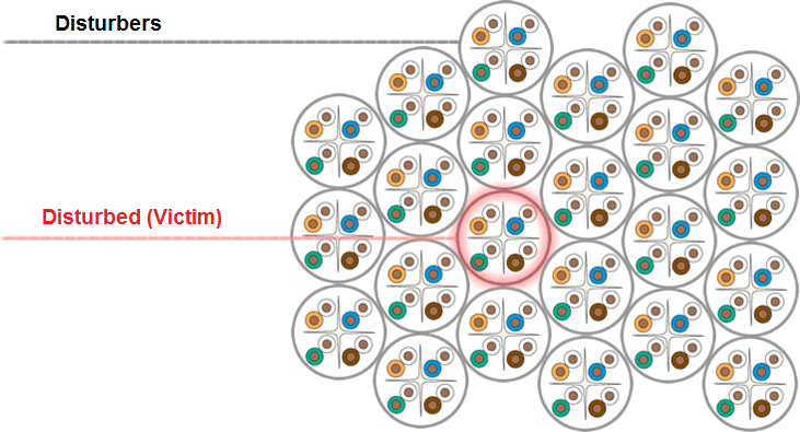
Alien crosstalk is the coupling of noise from one cable link to another. This happens if one cable is surrounded by many other cables in a bundle. We identify the cables that surround a cable in a bundle as Disturbers. Cables that can suffer from noise coupling from other cables are identified as the Disturbed cable or (Victim).
Why is it important?
The surrounding cables (Disturbers) will impact the ability of the disturbed cable (Victim) to transmit data. This becomes more important as we increase the bandwidth requirement of cables for faster applications. You might think that using shielded cables i.e. (where there is at least an outer shield) then alien crosstalk would not be a problem. However, if the shield is not terminated correctly even a shielded system can fall foul of alien crosstalk.
How do we Measure Alien Crosstalk? (With a DSX-5000)
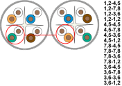
Basically we measure alien crosstalk between each pair of each Disturber cable to each pair of the Disturbed cable in a cable bundle. That means 16 PSANEXT (Power Sum Alien Near End Crosstalk) measurements between each disturber cable to the disturbed cable. We do this at the near-end for each disturber to the disturbed cable pair in the bundle.
First we identify the potential Disturbed cable that is surrounded by Disturbers, not including cables’ connectors that are adjacent to gaps. For Disturbers, we pick cables in the same bundle that surround the Disturbed cable. These are the cables where the connectors are likely to cause the majority of the ANEXT.
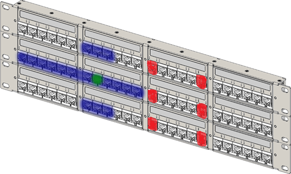
- The connector shown in green identifies a potential good disturbed cable connector.
- The connectors shown in red, identify cable connectors in a patch panel that would not make good disturbed cables.
- The connectors shown in blue identify potential good Disturber cable connectors in the same bundle as the Disturbed cable.
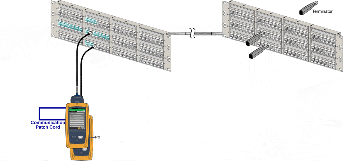
We make an ANEXT measurement with the Master unit of the DSX-5000 connected to the Disturbed (victim) at the near-end with a terminator at the far. The DSX-5000 remote unit is connected to the near-end of the Disturber with a terminator attached at the far end. The Master unit and remote are then connected together via the RJ45 communication ports to enable them to synchronise the tests being made. The measurements are then made on the Disturbed (Victim) as below for each Disturber.
For each test the Main unit of the DSX-5000 CableAnalyzer tester remains connected to the Disturbed (Victim) cable. Each time a measurement of Disturbed (Victim) is completed for one Disturber, the remote unit and the terminator are moved to the next Disturber to make the next test, this is continued until all the Disturbers in the bundle have been measured for that Disturbed cable.
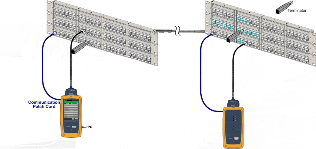
Alien Crosstalk also requires a measurement to be made from the far-end. This is the PS AACR-F (Power Sum Alien Attenuation Crosstalk Ratio Far End) measurement. This is performed in the same way as PS ANEXT but the setup is different. The Main unit is connected to the Disturbed cable connector as before. However, the remote unit is connected at the far end and the terminator at the near end as in the diagram below. In addition, the communication cable between the master and remote unit is connected through one of the horizontal RJ45 links.
For each test the Main unit of the DSX-5000 tester remains connected to the Disturbed (Victim) cable. Each time a measurement of Disturbed (Victim) is completed for one Disturber, the remote unit and the terminator are moved to the next Disturber to make the next test, this is continued until all the Disturbers in the bundle for one Disturbed cable have been completed.
What do the standards say about Alien crosstalk measurement requirements?
The ANSI/TIA-568-C.2 and ANSI/TIA-1152 identify that PS ANEXT and PS AACR-F measurements are required for compliance of Category 6A systems and are not optional. The values and methodology are described in ANSI/TIA-568-C.2.
The ISO/IEC 11801:2011 Edition 2.2 and IEC 61935-1 define PA ANEXT and AACR-F as normative for Field testing. i.e. normally required if not met by design (Specified in section A.2.11). If the coupling attenuation of ClassEA or F permanent links or CP links is at least 10dB better than the corresponding channel coupling attenuation requirements (see clause 6), and Class FA permanent links or CP links are at least 25dB better than the corresponding channel coupling attenuation requirements (see clause 6) then the requirements are met by design. Unfortunately, there is no way for you know the coupling attenuation, even with a field tester!
| Installation size | Sample size |
| (No. of total links) | (No. of links to test) |
| 3 – 33 | 100% |
| 34 – 3,200 | 33 |
| 3,201 – 35,000 | 126 |
| 35,001 – 150,000 | 201 |
| 150,001 – 500,000 | 315 |
What do the standards say about the number of sample tests required on an installation?
The ISO/IEC 14763-2 defines that an equal number of short, medium and long links should be test to an equivalent acceptance quality level (AQL) of 0.4% as defined in ISO 2859-1 for link populations up to 500,000 links. So the maximum number of Disturbed bundles you would have to measure would be between 3 and 315.
However, did you know that according to IEC 61935-1 in sections 5.4.2 through 5.4.6 if you measure the ANEXT and AFEXT and process the data as described in 5.4.7 for the links with the highest insertion loss (read longest links) if your results for three of these links show a margin of 5 dB for PS ANEXT and PS AACR-F, then you can stop testing the highest insertion loss links (longest links). This is also the case if you measure three of the lowest insertion loss links (read shortest links) and also the median insertion loss links (read median length links).
So I hope that is much clearer! You are required to test an installation for Alien Crosstalk. There is a method of testing which is to measure the PS ANEXT and PS AACR-F on a Disturbed link in a minimum of three bundles for each of the short, median and long links. If these pass with 5dB or greater margin then you can stop. If not, you have to continue testing to an AQL sample size of 0.4%.
 Barry Lindsley has 44 years of experience in the Test and Measurement industry working with Tektronix, Fluke and Fluke Networks. Of which 23 years have been in the networks business. During this time he was working in either technical or combined technical and marketing roles. He also chaired the TIA (UK) Sig 11 group chairman working on CAT5E testing. For the last 3 years Barry has owned a consulting company which provides networking technical and marketing professional services.


