On cursor placement when making an OTDR measurement
August 2, 2017 / Standard and Certification
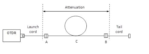
Testing and characterizing a permanent link with an OTDR requires the measurement of connector attenuations A/B and fiber loss C. To make this measurement, a launch and tail cord are needed (see Figure 1).
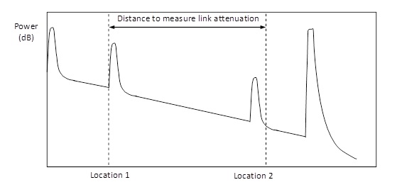
If making manual measurements, one may think to place cursors as show in Figure 2 to match the reference planes of Figure 1. While this seems to make sense, it can lead to measurement errors. If making a manual measurement with the cursor at Location 2, make sure the cursor is on the linear part of the backscattering not on the tailing part. Needless to say, an automatic measurement will provide a better result as explained below.
When an automatic OTDR measurement is made, the cursors will be placed as shown in Figure 3. Note the difference in cursor location at Location 2 from the cursor placement in manual mode.
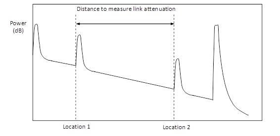
According to IEC 61280-1 and IEC 61280-2, the standards defining attenuation measurements for installed fiber optic cabling, the proper placement of the two cursors is located at the abrupt change of curvature before the two peaks that represent the two connectors, as shown in Figure 3. Looking at this might make you think that the OTDR is making a significant error in the measurement by ignoring the loss in the connector. But there’s something going on here that isn’t obvious.
Rather than just “eyeballing” where the second cursor should go as in figure 2, OTDR’s use the measurement method defined in the standard known as the five cursors method. This is because five cursor positions are needed to complete the measurement. The result is a more precise measurement. Here’s how it works.
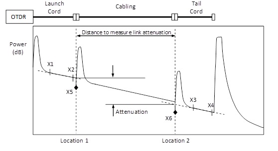
Figure 4 shows cursor positions on the backscattering trace. X1 and X2 define the area of linear regression of the launch test cord. X3 and X4 define the area of linear regression of the tail cord. X5 needs to be placed at Location 1. X6 is shown as the “6th cursor” for illustration purposes and needs to be placed at Location 2.
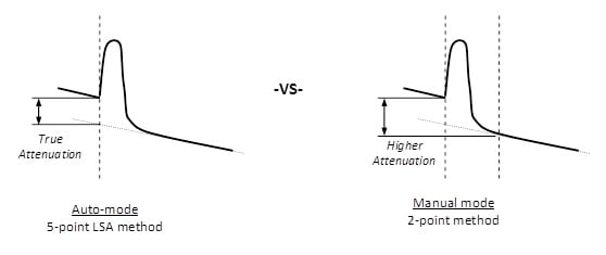
Referring to Figure 5, let’s take a closer look at what is going on at Location 2 to clear up any confusion. In auto-mode, the OTDR uses the 5 cursor method (e.g., 5-point) but in manual mode, an OTDR will only allow a 2 point loss measurement (i.e., using two cursors). Note that the manual mode method measures higher attenuation and has higher uncertainty. Uncertainty will be worse with wider pulse widths but will decrease when the backscatter has a lower backscatter slope (i.e., 1310 nm and 1550 nm measurements).
Note: all OTDR loss measurements are made by comparing two backscatter levels.
If after an automatic OTDR measurement you see the cursor placement at the start of the connector loss, don’t be alarmed. The OTDR is making a proper measurement that is also standards compliant. A cursor placement at Location 2, as shown in Figure 2, may not necessarily mean the OTDR made a measurement using that location. It could be the cursor was placed there to correlate the link reference plane.
Publications récentes Tout voir >
Torons ou câbles rigides
2024-3-06
Qu’est-ce que la perte de retour ?
2023-2-14
Plus de publications générales Tout voir >
Torons ou câbles rigides
2024-3-06


©2006-2021 Fluke Corporation。保留所有权利。
RM2011, 20/F, SCITECH Tower, 22 Jianguomenwai Avenue, Chaoyang District, Beijing, China
地址:北京市朝阳区建国门外大街22号赛特大厦20层2011室
联系电话:400-8103435
沪ICP备11037028号-15![]()