On bi-directional testing with a light source and power meter
August 9, 2017 / Standard and Certification
In the 2014 version of ISO/IEC 14763-3, testing of optical fiber cabling, unidirectional testing for permanent links is required. In specific cases, bi-directional testing is required. However, ISO/IEC 14763-3 provides no information on how a bi-directional test should be done - this article explains how.
When Bi-Directional Testing is Required
Per ISO/IEC 14763-3, if the link comprises a single fixed cable and terminating connectors, a unidirectional testing may be performed. If the link or channel is more complex, or where there is risk that components within the cabling under test cause differences in the attenuation depending on the direction of transmission, bi-directional measurements shall be carried out.
Bi-Directional Testing with a Light Source and Power Meter
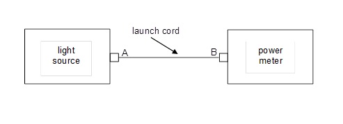
1) Set a reference with a reference grade launch cord using the 1-cord method (see Figure 1).
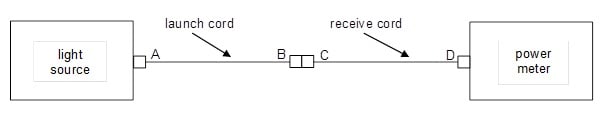
2) Verify low loss at the connector pair B-C between the launch cord and receive cord (see Figure 2).
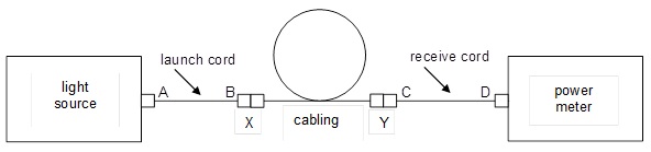
3) Test in one direction. Do not disconnect the launch cord from the light source. Attach the launch cord to one end of the cabling and the receive cord and power meter to the other end of the cabling (see Figure 3).
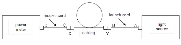
4) Then, without disconnecting the launch cord from the light source, move to connection Y. Move the receive cord and power meter to connection X (see Figure 4).
Note: Use the worst of the two measurements as the final test result. If the difference in the two measurements is greater than 0.2 dB, the reference could be wrong, something may be wrong with the test cord, or there may be a bend in the fiber.
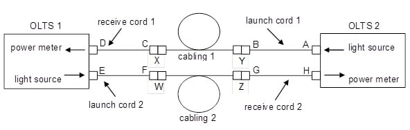
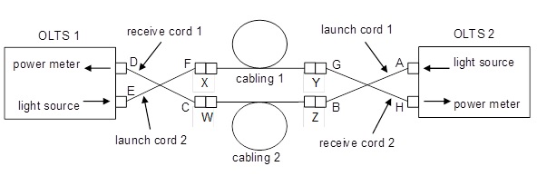
Bi-Directional Testing with an Optical Loss Test Set
If using an optical loss test set (OLTS) containing a power meter and light source in one box, simply swap the connections after the test is run at the patch panel or fiber distribution center, being careful to maintain the mated connections to the test equipment (see Figure 5 and 6).
Regardless of the type of equipment, the key thing to remember is to NOT disconnect the launch or receive cord from the tester once you’ve set the reference and verified the launch and receive cords. Doing so can add significant uncertainty to your measurements.
Usually, bi-directional testing is needed when testing a permanent link with an OTDR. But for some specific link configurations, it may be needed when using a light source and power meter. In that case, the method outlined in this article should be used. Who knows, maybe ISO/IEC 14763-3 will adopt this method in its next revision cycle.
Publications récentes Tout voir >
Torons ou câbles rigides
2024-3-06
Qu’est-ce que la perte de retour ?
2023-2-14
Plus de publications générales Tout voir >
Torons ou câbles rigides
2024-3-06


©2006-2021 Fluke Corporation。保留所有权利。
RM2011, 20/F, SCITECH Tower, 22 Jianguomenwai Avenue, Chaoyang District, Beijing, China
地址:北京市朝阳区建国门外大街22号赛特大厦20层2011室
联系电话:400-8103435
沪ICP备11037028号-15![]()